Scan to BIM: Workflow, Cost, Checklist and Accuracy
 Matúš Koleják
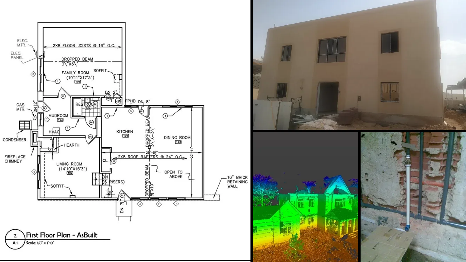
Most renovation projects still start with a tape measure, a set of old drawings nobody fully trusts and a site visit where someone writes dimensions on a printout. Scan to BIM replaces that with a measured 3D record of the building as it is today, and a model that every consultant can work from.
This guide is written for the person ordering or checking that work: an architect, owner, facility manager or contractor. It walks through the workflow the way a project actually runs it, then gives you the three things most Scan to BIM pages leave out: what the published prices really say (and why they disagree), a scope checklist you can paste into a request for quotation, and a step-by-step check of the finished model before you accept it.
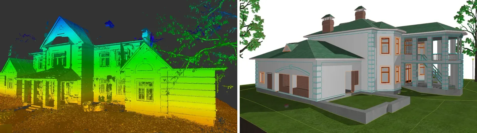
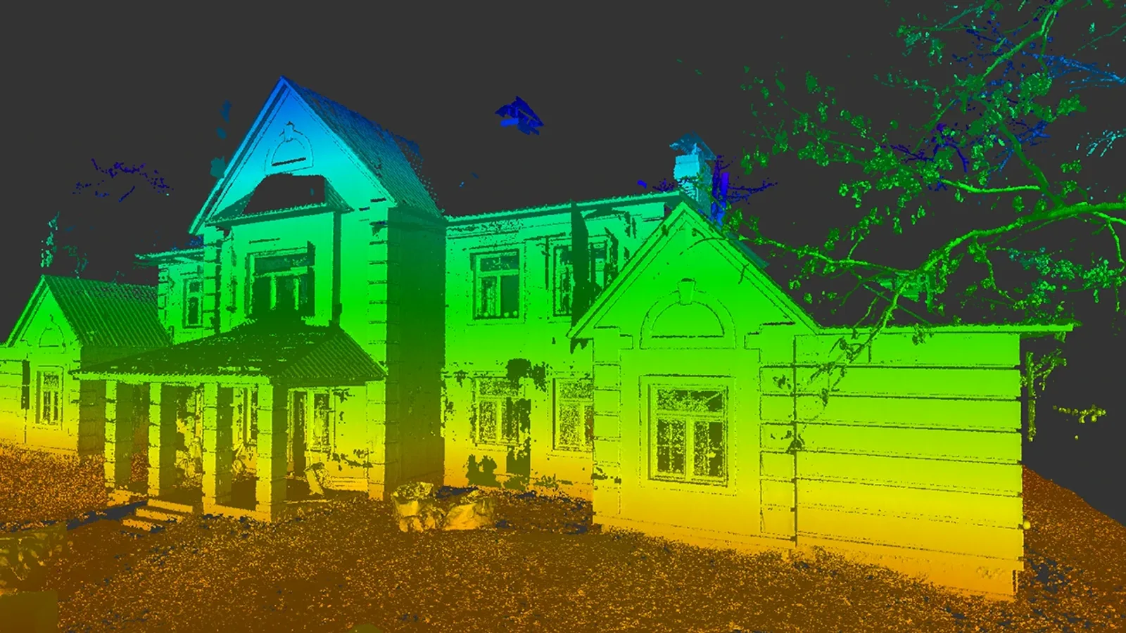
The same house twice: the registered point cloud, coloured by height (left), and the Archicad model traced from it (right). The cloud measures every surface the scanner saw, trees included; the model keeps only what the scope asked for. Project: Scan to BIM 2-storey House in Archicad by Bohdan Medynskyi on Behance.
What is Scan to BIM?
Scan to BIM is a reality capture workflow with two halves. The scan half measures the building: a laser scanner on a tripod spins and records the distance to everything it can see, producing a point cloud, a set of millions of 3D points, usually coloured from the scanner's own photos. The BIM half interprets the measurements: a modeller builds real BIM objects (walls with a thickness, floors with an edge, doors in openings, beams, ducts) using the cloud as an exact underlay.
The point cloud alone is not a BIM model. It knows where surfaces are, but not that a surface is a wall, how thick the wall is, what is behind the plaster or which room is on the other side. That interpretation is the expensive part, and it is why Scan to BIM is priced by the area and the level of detail modelled, not by the scan alone.
Typical reasons to commission it:
- Renovation and refurbishment, where the design has to fit an existing structure exactly.
- Extensions and change of use, where new floors, stairs or services must tie into what is there.
- Building services retrofits, where new ducts and pipes have to be routed around existing ones.
- Heritage documentation, where the record itself is the deliverable.
- Construction verification, comparing what was built with the design model before it is covered up.
- Facility management, giving an owner a usable model of a building that was designed before BIM.
| What it is | Knows what objects are? | Typical use | |
|---|---|---|---|
| Point cloud | Millions of measured points, often coloured | No | Measuring, underlay, visual record |
| Mesh | Triangulated surface built from the points | No, unless classified | Visualisation, quick massing, some automated workflows |
| As-built drawings | 2D plans, sections, elevations drawn from a survey | Only as labels | Permits, traditional design |
| Scan to BIM model | BIM objects modelled over the cloud | Yes: walls, slabs, doors, MEP, with properties | Design, coordination, quantities, facility management |
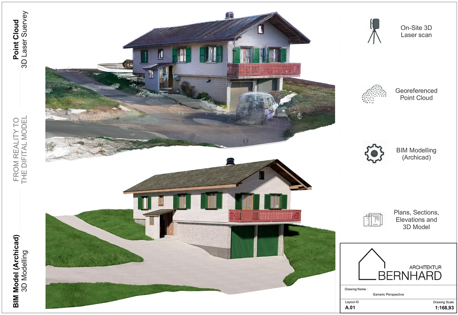
One real project from start to finish: the laser survey of a house (top) and the Archicad model built from it (bottom). Project: Käser Rickli-Käser, Point Cloud to BIM model by Exequiel Watters on Behance.
The Scan to BIM workflow in 6 steps
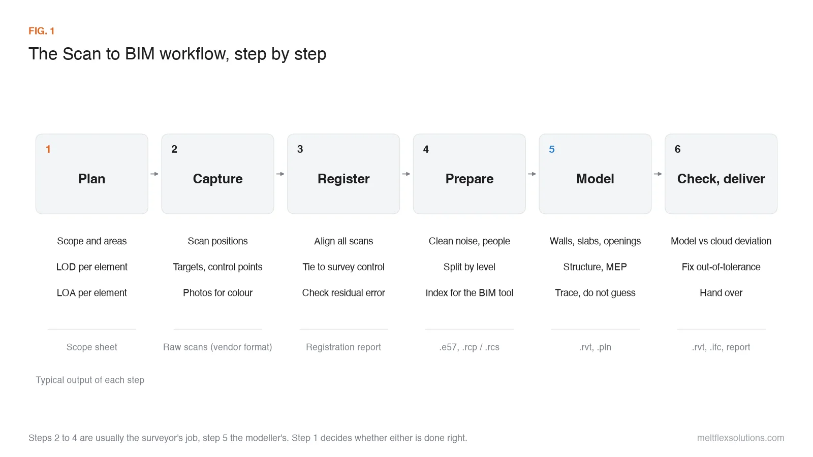
1. Plan the scope before anyone scans
The scope decides everything downstream, so write it as a table, not a sentence. For each area of the building and each element category (walls, floors, ceilings, stairs, doors, windows, structure, ducts, pipes, cable trays, furniture), state:
- Whether it is modelled at all. Ceiling voids, plant rooms and roofs are the usual surprises.
- The LOD, the level of development: LOD 200 for a generic placeholder of approximately the right size, LOD 300 for the element at its measured size and position. More on this below.
- The LOA, the level of accuracy the element must meet.
- The deliverable: native Revit or Archicad file, IFC, 2D sheets, or all of them, plus the registered point cloud itself.
A vague scope such as "full BIM model of the building" is the most common reason a Scan to BIM project goes over budget: the surveyor prices one thing, the modeller another, and the client expected a third.
2. Capture: scan positions, control and targets
The surveyor sets the scanner up at a series of positions, close enough that each scan overlaps the previous ones, so that every surface is seen from at least one position and the scans can be joined. A current tripod scanner such as the Leica RTC360 is rated at up to two million points per second and, according to its datasheet, finishes a full dome scan with HDR photos in under two minutes per position. With scanners that fast, much of the time on site goes into moving the tripod and planning positions, not into the scan itself.
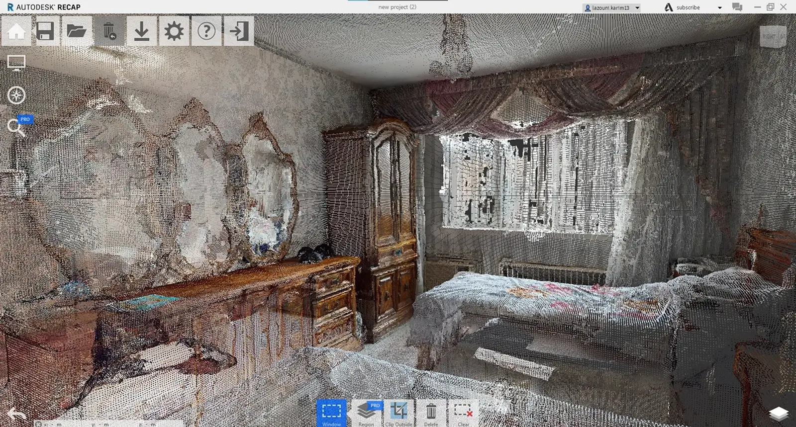
A furnished bedroom as the scanner saw it, in Autodesk ReCap. Note the black holes behind furniture, the noisy mirrors and the broken-up window: walls behind a wardrobe are simply not in the data. Project: Modeling a house in Revit from a point cloud by Abdelkrim Lazouni on Behance.
For anything that has to fit into real-world coordinates, such as a site plan, a neighbouring building or a construction set-out, the scans are tied to survey control: points measured with a total station or GNSS receivers, sometimes marked with targets that the scanner can recognise.
Things a scanner cannot see, and the scope should say how to handle:
- Hidden elements. Anything behind plaster, above a closed ceiling or inside a wall is not in the cloud. If services in ceiling voids matter, tiles have to be lifted or the void scanned separately.
- Glass, mirrors and polished surfaces, which reflect or pass the laser and create ghost points.
- Very dark or wet surfaces, which return weak signals.
- People and traffic, which leave streaks to be cleaned out later.
3. Register the scans into one cloud
Each scan is recorded in the scanner's own coordinates. Registration aligns all of them into one cloud, using overlapping geometry, targets or both, and then fits the result to the survey control. Registration software reports how well the scans agree with each other. Ask for that report. A model can only be as accurate as the registered cloud, and a poorly registered cloud produces walls that appear doubled or slightly skewed.
How far apart the scan positions are, and how much they overlap, decides how well registration works. In this short clip, a reality capture specialist from Leica Geosystems explains how to space scans for reliable registration:
4. Prepare the cloud for modelling
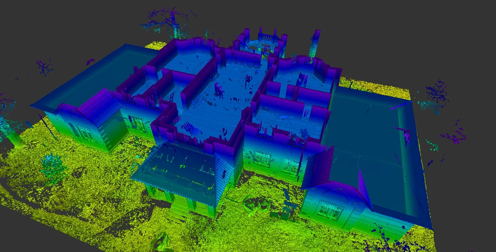
The same cloud seen from above. Sliced by level and viewed in plan, it becomes the underlay a modeller traces walls over. Project: Scan to BIM 2-storey House in Archicad by Bohdan Medynskyi on Behance.
Before modelling, the cloud is cleaned (people, cars, reflections, stray points), often split by level or zone so that the BIM software only loads what is needed, and converted to a format the modelling tool reads. The vendor-neutral exchange format is E57, standardised as ASTM E2807. Revit links Autodesk's indexed formats, RCP (a project of several scans) and RCS (a single scan), which ReCap or Revit's own indexer creates from E57 and other raw formats. Archicad imports E57 and XYZ files directly.
5. Model over the cloud
The modeller sets up levels and grids from the cloud, then traces elements in plan and section views cut through it: walls first, then floors and roofs, openings, stairs, structure, and services if they are in scope. The rule that separates a good Scan to BIM model from a bad one is simple: trace, do not guess. Where the cloud shows nothing, for example behind a wall or above a ceiling, the model should either leave the element out or mark it as assumed, never invent it silently.
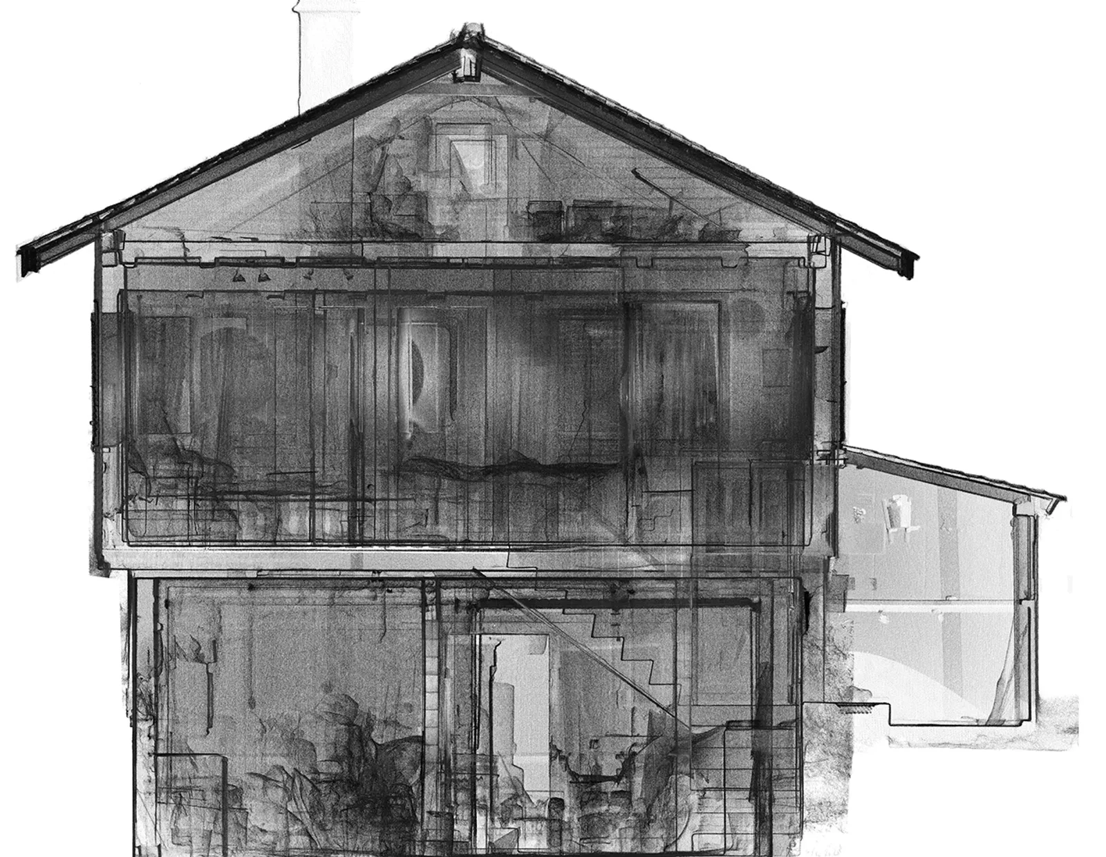
A section cut through the point cloud of a two-storey house. Walls, slab edges, the stair and the roof build-up are all readable, which is why modellers trace in sections, not only in plan. Project: Käser Rickli-Käser, Point Cloud to BIM model by Exequiel Watters on Behance.
Real buildings are not straight. A wall that leans 15 mm over its height, a floor that dips in the middle or a corridor that is not quite square have to be modelled either as they are (more expensive, more accurate) or as idealised elements within a stated tolerance. The scope should say which.
If you are new to cutting and reading sections, our guide to section views explains how plans and sections are cut through a model.
6. Check the model against the cloud and deliver
A good provider compares the finished model with the point cloud and reports the deviation, typically as a colour map showing where the modelled surfaces sit more than the agreed tolerance away from the measured points. Out-of-tolerance elements are fixed or documented. The delivery should include the native model, an IFC export for anyone not on the same software, the registered point cloud and the registration and deviation reports.
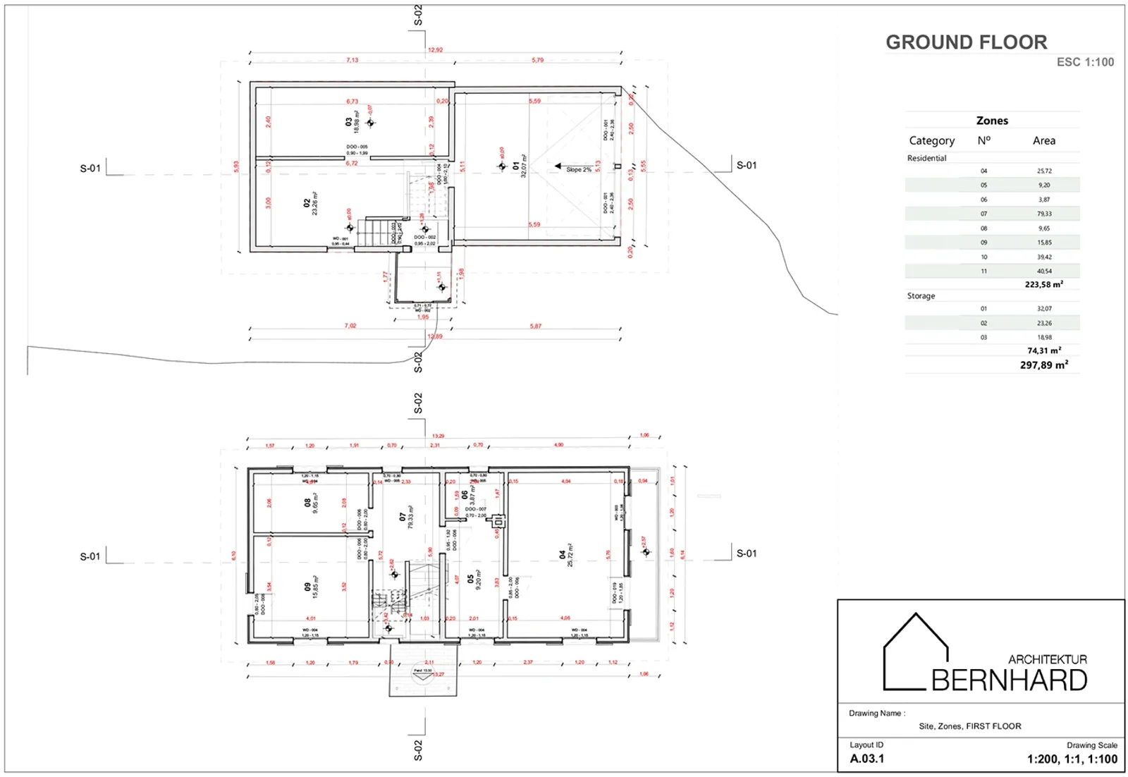
The deliverable most clients actually use: plans with room areas, generated from the scanned model. Project: Käser Rickli-Käser, Point Cloud to BIM model by Exequiel Watters on Behance.
The video below shows a current version of steps 4 and 5 in Revit 2026, including Autodesk's newer mesh-based workflow with ReCap Pro:
LOD and LOA: the two numbers every scope needs
Scan to BIM contracts often mix up two different things.
LOD (Level of Development) says how far each modelled element is developed: LOD 200 is a generic wall of roughly the right thickness, LOD 300 is the wall at its measured size, shape and position. The BIMForum LOD Specification has a special level for this kind of work, LOD 500, which does not mean "more detail than LOD 400" but "an existing or as-built condition, developed from observation, with its accuracy stated". For that accuracy statement, BIMForum points to the USIBD Level of Accuracy specification.
LOA (Level of Accuracy) says how close the measured or modelled position must be to reality. The US Institute of Building Documentation defines five levels:
| Level | Accuracy band (95% confidence) | Example use (our reading, not part of the spec) |
|---|---|---|
| LOA10 | Coarser than 50 mm | Massing, rough area checks |
| LOA20 | 15 to 50 mm | General planning, space layouts |
| LOA30 | 5 to 15 mm | Detailed renovation design |
| LOA40 | 1 to 5 mm | Precise interfaces, prefabrication, structural connections |
| LOA50 | Up to 1 mm | Specialist and industrial measurement |
A note on sources: the official USIBD LOA Specification (version 3.1) sits behind a free account on usibd.org, and we have not quoted it directly. The bands above are as quoted by secondary sources, and the LOA20 band (15 to 50 mm at 95% confidence) is confirmed by NavVis. Use the official document as the reference in a contract, and treat the right-hand column as examples, not requirements.
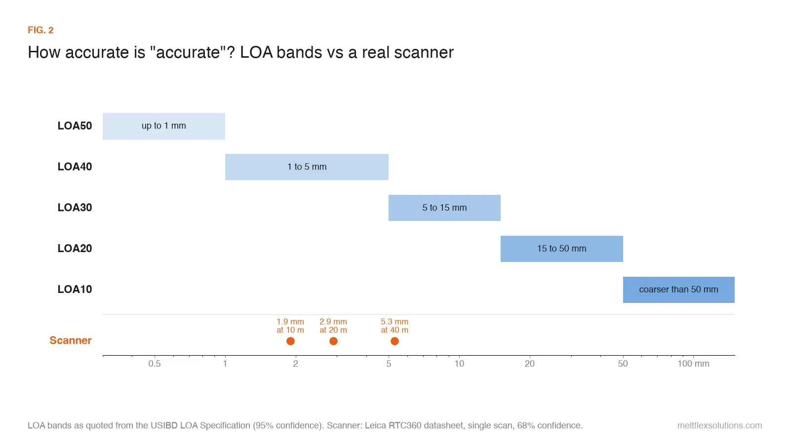
Three practical lessons from that chart:
- Accuracy depends on distance. The same scanner is about 2 mm accurate at 10 m and over 5 mm at 40 m, according to its datasheet. A long facade scanned from far away will not reach the accuracy of a room scanned from its centre.
- Datasheets and specifications use different confidence levels. The Leica RTC360 datasheet states its accuracy at 68% confidence; LOA bands are at 95%. The 95% figure for the same scanner is larger, by about 1.5 times if the datasheet value is a 3D radius and about 2 times for an error measured in one direction, assuming normally distributed errors. Registration error then comes on top.
- The model is less accurate than the cloud. A wall modelled as one flat plane through a wavy plaster surface cannot be more accurate than the wall is flat. Specify the accuracy of the point cloud and of the modelled elements separately.
The cost follows the numbers. A tighter LOA means more scan positions, shorter distances, tighter registration and slower modelling, so it is worth setting it per element: a strict level where new work has to fit existing work exactly, a looser one everywhere else.
How much does Scan to BIM cost?
Search for a Scan to BIM price and you will find confident per-square-foot numbers. We compared three detailed 2025 to 2026 price guides published by US scanning firms. They do not agree:
| Published guide | LOD 300 rate | What it covers |
|---|---|---|
| Arrival 3D (2025) | $0.18 to $0.50 per sq ft | All-in, scanning plus Revit model |
| iScano (January 2026) | $0.40 to $1.20 per sq ft | All-in, commercial office, architecture and structure |
| The Future 3D (March 2026) | $1.50 to $3.50 per sq ft, plus $0.20 to $0.70 for scanning | Third-party modelling rates, scanning priced separately |
Applied to the same job, a 2,000 m² (about 21,500 sq ft) office modelled at LOD 300, those rates give:
| Using the rates of | Estimated total |
|---|---|
| Arrival 3D | $3,870 to $10,750 |
| iScano | $8,600 to $25,800 |
| The Future 3D | $36,550 to $90,300 |
That is a spread of more than twenty times for one building. Two honest conclusions follow. First, these are marketing pages from companies that sell the service, not audited market data, and each describes a slightly different scope. Second, a per-square-foot figure without a written scope is meaningless: "LOD 300" with or without structure, ceilings, MEP, families and sheets is not the same product.
What the guides do agree on is what moves the price:
- MEP. Modelling ducts, pipes and trays is the biggest single cost driver. iScano puts MEP-dense plant rooms at $2 to $8+ per sq ft, several times an office floor.
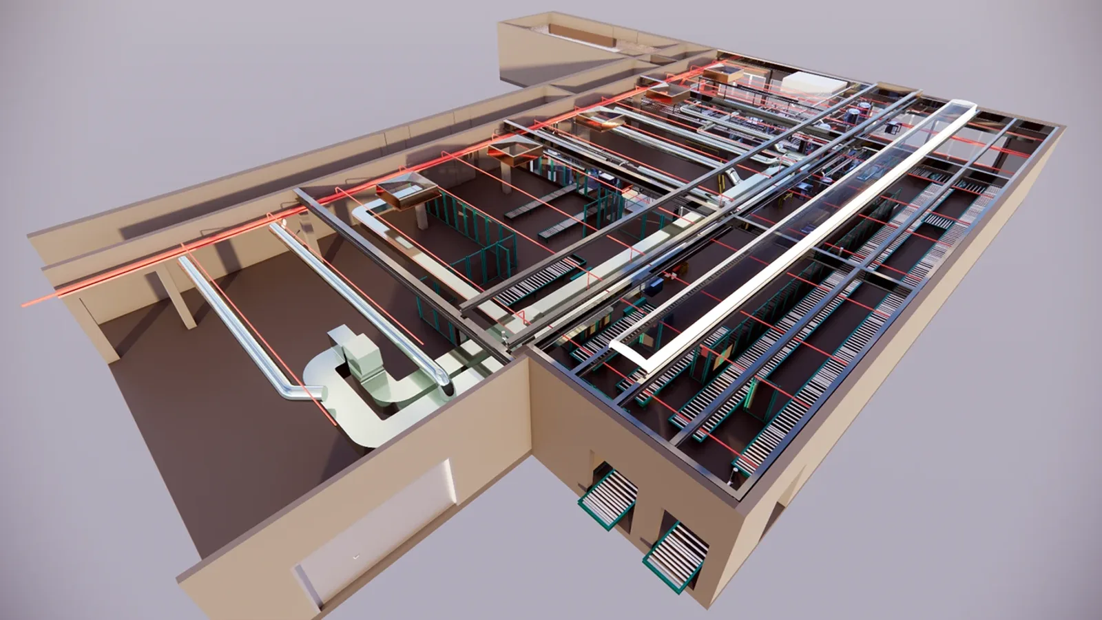
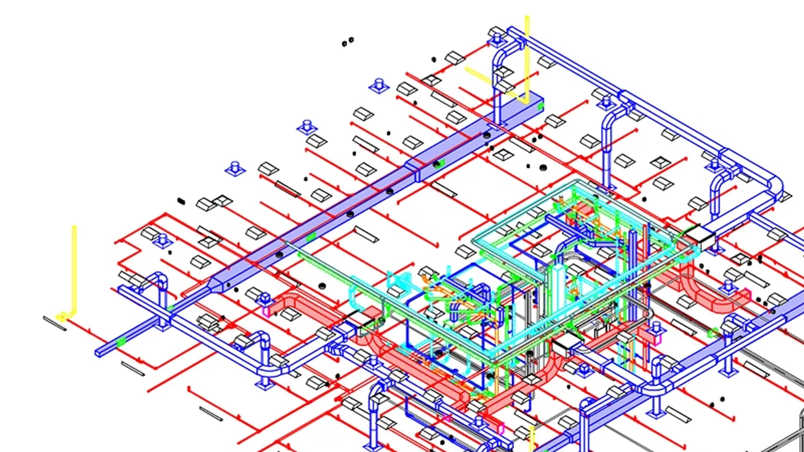
Building services modelled from a scan. Every pipe and duct is a separate element to trace and check, which is why MEP scope multiplies the price. Project: Point cloud to Revit model by Nuovotech Engineers on Behance.
- LOD and LOA. Each step up means more scan positions, tighter registration and slower modelling.
- Access and working hours. Occupied buildings, night work (iScano quotes a 1.5x labour premium) and restricted areas all add field time.
- Survey control. Tying the scan to a licensed land surveyor's control network adds a fixed fee (iScano: $3,000 to $5,000).
- Minimum fees. Small jobs pay for mobilisation: iScano quotes $2,500 to $3,500 as a minimum for a house.
- Point cloud only. Skipping the model is far cheaper; iScano says 60 to 70% less. If you have a modeller in-house, buying only the registered cloud can make sense.
How to get quotes you can actually compare: send every provider the same scope table (the checklist below), ask for the price split into field work, registration and modelling, and ask what is excluded. A quote that is half the others usually models less, not the same for less.
Scan to BIM checklist: the scope to send providers
Paste this into your request for quotation and fill in every line. If you cannot answer a line, that is a question to settle before scanning, not after.
SCAN TO BIM SCOPE

BUILDING
  Name, address:   [...]
  Floor area:      [m² or sq ft, gross]
  Included:        [floors, roof, basement, plant rooms,
                    ceiling voids, exterior, site]
  Excluded:        [...]
  Access:          [occupied? hours? escorts? roof?]

POINT CLOUD
  Accuracy (LOA):  [e.g. LOA20, LOA30 at new interfaces]
  Survey control:  [tie to surveyor control / not needed]
  Deliver:         [registered E57 + RCP, registration
                    report]

MODEL
  Software:        [e.g. Revit 2026 / Archicad 30, IFC4]
  Disciplines:     [arch / structure / MEP, smallest
                    pipe or duct modelled]
  LOD per element: [walls 300, doors 300, ceilings 200,
                    furniture not modelled ...]
  Uneven surfaces: [as measured / idealised within X mm]
  Hidden elements: [omit / model as assumed + mark]
  Standards:       [our template, naming, levels,
                    shared coordinates]

DELIVERABLES
  [native model, IFC, sheets?, deviation report,
   list of assumptions]

ACCEPTANCE
  [deviation check and tolerance, review rounds,
   deadline]
Three lines in that template do most of the work. LOD per element stops the "full model" argument. Hidden elements decides whether the modeller is allowed to guess. Acceptance gives you a contractual way to reject a model that does not fit the cloud.
How to check a Scan to BIM model before you accept it
Most clients open the model, see walls in the right places and sign off. These checks take an afternoon and catch most of what goes wrong:
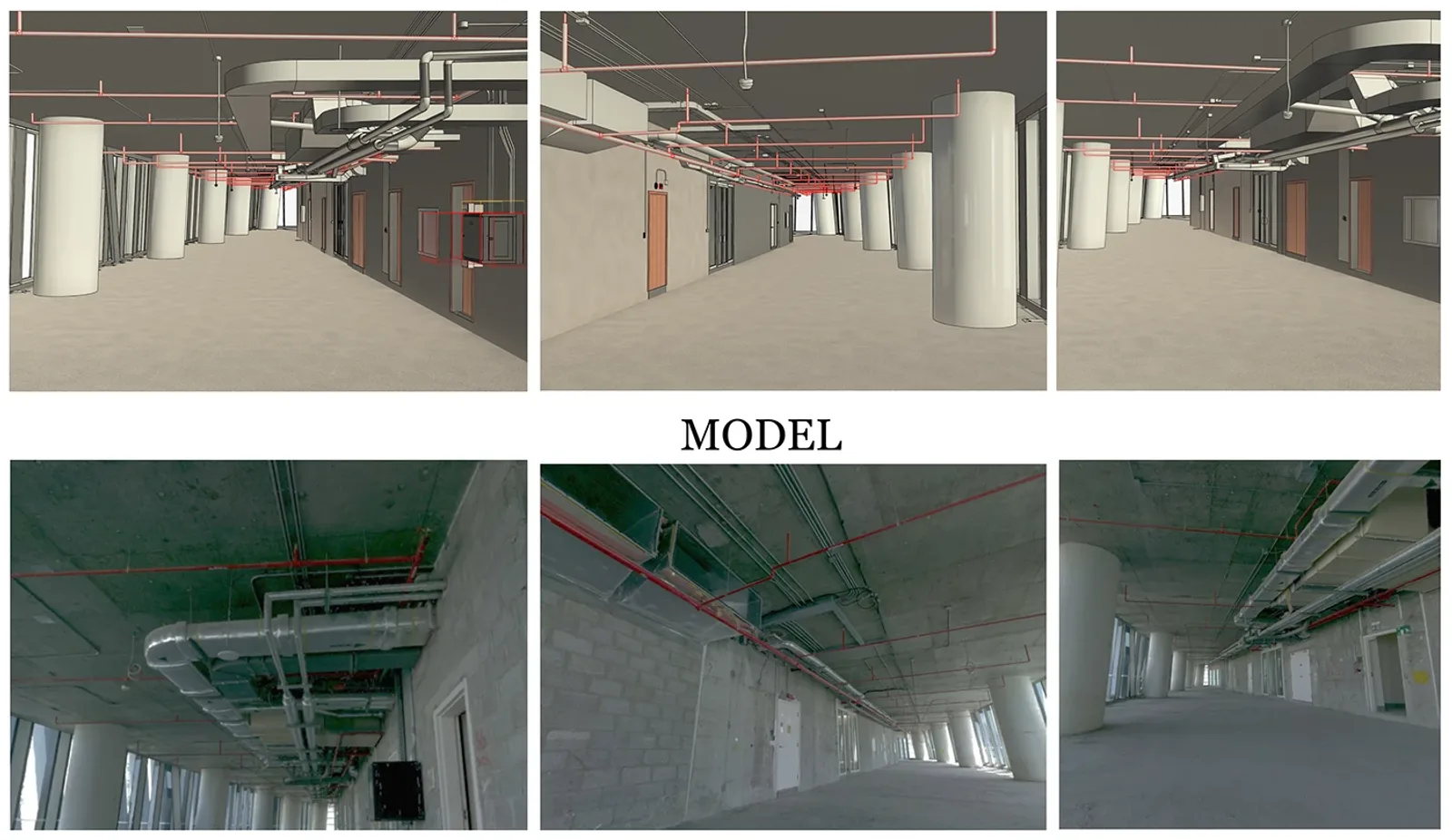
Model (top) against the scanned reality (bottom) on an office floor of the KAFD tower in Riyadh. Comparing the same viewpoints side by side is the quickest visual check before running a numeric deviation test. Project: KAFD Tower Scan to BIM by Eyad Ahmed on Behance.
- Read the registration report. It should state how well the scans agree with each other and with any survey control. If a provider cannot produce one, the accuracy claim is unsupported.
- Overlay the model on the cloud in sections. In Revit, link the RCP, then cut sections at a few grid lines and at random places, including the middle of long walls and at floor edges. Walls that drift off the points, or doubled surfaces in the cloud itself, show up immediately.
- Run a cloud-to-model deviation check. Export the model as a mesh (FBX or OBJ) and load it with the E57 into CloudCompare, which is free. Its cloud-to-mesh distance tool colours every point by its distance from the nearest model surface, and the histogram tells you what share of points lie within your tolerance. Ignore furniture and anything not in the modelling scope.
- Spot-check on site. Measure ten dimensions with a laser distance meter: room widths, ceiling heights, opening sizes, a long corridor. Compare them with the model. This catches unit and scale errors that no software check will.
- Check levels and heights. Floor-to-floor heights and finished floor levels are where idealised models most often differ from reality, and where new work most often fails to fit.
- Read the list of assumptions. Everything modelled without being seen in the cloud should be listed or marked in the model. An empty list on an old building usually means nobody wrote it down, not that nothing was assumed.
- Open the IFC. Even if you work in Revit, open the IFC export in a free viewer and check that elements have the right classes and storeys. The next consultant may not use your software.
Scan to BIM software
No single program does the whole job. Most projects use one tool to register and prepare the cloud and another to model.
| Software | Role in the workflow | Notes |
|---|---|---|
| Autodesk ReCap Pro | Registration, cleaning, indexing to RCP/RCS | The bridge to Revit. The 2026 release adds local scan-to-mesh, a mesh editor with classification and a Revit plugin that brings meshed geometry into Revit as families |
| Autodesk Revit | Modelling over the cloud | Links RCP and RCS; raw formats such as E57 are indexed first |
| Graphisoft Archicad | Modelling over the cloud | Imports E57 and XYZ point clouds directly |
| Leica Cyclone REGISTER 360 | Registration | Common with Leica scanners; exports E57 for other tools |
| FARO SCENE | Registration and processing | The usual tool for FARO Focus scanners |
| Trimble RealWorks | Registration and processing | Common with Trimble scanners |
| ClearEdge3D EdgeWise | Semi-automated extraction | Finds pipes, ducts, walls and structural members in the cloud and builds them in Revit |
| CloudCompare | Free, open-source viewing and processing | Cleaning, comparing clouds, cloud-to-mesh deviation checks |
Once the as-built model exists, it is usually coordinated against the new design and the services models; our guide to clash detection in BIM covers that step. If you are still choosing the BIM tool itself, our comparison of the best BIM software covers Revit, Archicad and the alternatives with prices.
Point cloud file formats
| Format | What it is | Opens in |
|---|---|---|
| .e57 | Vendor-neutral standard (ASTM E2807) for points, colour, intensity and scanner images | Almost every registration and BIM tool; Revit after indexing |
| .rcp / .rcs | Autodesk's indexed project and scan files | Revit, AutoCAD, Navisworks, ReCap |
| .las / .laz | Lidar exchange format, compressed as LAZ | Mainly aerial and mobile lidar, GIS tools |
| .pts / .xyz / .txt | Plain-text points, one per line | Almost anything, but large and without scan structure |
| .fls, vendor raw | The scanner's own raw format | The vendor's registration software |
When you order a survey, ask for E57 as well as whatever the modeller needs. It keeps the data usable if you change software or consultants later.
Scan to BIM challenges and common mistakes
- No scope table. "Model everything" means something different to every party.
- One LOA for the whole building. Facades for permit drawings and a steel connection for prefabrication do not need the same accuracy.
- Forgetting hidden spaces. Ceiling voids, risers and roofs are only in the cloud if someone opened them.
- Not asking for the registration report. Errors here propagate into every element.
- Modelling what is not in the cloud without marking it as assumed.
- Delivering only a native file. Without IFC and E57, the next consultant may not be able to use the work.
- Treating the model as a substitute for structural investigation. A scan measures surfaces, not what a wall is made of or whether a beam is sound.
Alternatives to laser scanning
Terrestrial laser scanning is the reference method, but not the only one:
- Mobile and handheld SLAM scanners are carried or wheeled through the building and capture far faster, usually with lower accuracy than a tripod scanner. They suit large floors and LOA20 work.
- Photogrammetry builds a cloud from overlapping photos or drone images. It is strong on facades and roofs, weaker indoors and on plain white walls.
- Phone and tablet lidar is good enough for a quick room record, furniture planning or a client conversation, but not for a model a contractor will build from.
- Old drawings plus spot checks. When only paper plans exist and the budget is small, digitising them and checking key dimensions on site can be enough. If you only need 2D plans rather than a model, our guide to as-built drawings compares published prices for measured plans, from drafting-only to laser-scanned sets. Our guide on how to digitize a blueprint with AI covers that route, and how to read construction blueprints helps you judge what an old set is worth.
Frequently asked questions
What is Scan to BIM?
Scan to BIM is the process of capturing an existing building with a 3D laser scanner and modelling it as a BIM model from the resulting point cloud. The scans are registered into one cloud, and a modeller traces walls, slabs, openings, structure and services over it in software such as Revit or Archicad, producing an as-built model accurate to a specified level.
What is the difference between a point cloud and a BIM model?
A point cloud is a set of millions of measured 3D points: it shows where surfaces are but does not know what they are. A BIM model consists of objects such as walls, floors, doors and ducts, each with a type, dimensions and properties. Scan to BIM is the step that turns the first into the second.
How much does Scan to BIM cost?
It depends mostly on floor area, the LOD, whether MEP is modelled and how hard the site is to access. Published 2025 to 2026 US price guides quote LOD 300 anywhere from about $0.18 to $0.50 per square foot all-in to $1.50 to $3.50 per square foot for modelling alone, so a 2,000 m² office can be estimated at anything from under $4,000 to over $90,000. Treat those figures as a rough range and compare real quotes against one written scope.
What should a Scan to BIM scope include?
The areas included and excluded, the accuracy (LOA) of the point cloud, whether it is tied to survey control, the software and version of the model, the disciplines, the LOD for each element category, how hidden and uneven elements are handled, the deliverables (native model, IFC, point cloud, reports) and how the model will be checked and accepted.
What software is used for Scan to BIM?
Usually two kinds. Registration software such as Autodesk ReCap Pro, Leica Cyclone REGISTER 360, FARO SCENE or Trimble RealWorks joins the scans into one cloud. A BIM authoring tool such as Revit or Archicad is then used to model over it. Tools like ClearEdge3D EdgeWise can extract pipes, ducts and walls semi-automatically, and CloudCompare is a free option for checking and comparing clouds.
Can Revit open E57 files?
Revit works with Autodesk's indexed point cloud formats, RCP and RCS. When you insert a raw format such as E57, it has to be indexed first, either in Autodesk ReCap or with the indexer Revit launches when you insert a non-indexed file. The usual workflow is to register and clean the scans, save an RCP project in ReCap and link that into Revit.
What LOD is used for Scan to BIM?
Most architectural Scan to BIM work is modelled at LOD 200 to 300: elements at their measured size and position, without fabrication detail. The BIMForum LOD Specification uses LOD 500 for existing or as-built conditions developed from observation, and asks for the accuracy to be stated, for which it recommends the USIBD Level of Accuracy specification.
How accurate is Scan to BIM?
It depends on what is specified. A modern terrestrial scanner measures points to a few millimetres at typical indoor distances, and the USIBD accuracy levels run from LOA10 (coarser than 50 mm) to LOA50 (up to 1 mm). Most architectural projects ask for LOA30, 5 to 15 mm. The finished model is always somewhat less accurate than the cloud, because real surfaces are not perfectly flat.
Can AI automate Scan to BIM?
Partly. Tools can now classify points, build meshes and recognise standard elements such as walls, pipes and ducts, and Autodesk's ReCap Pro 2026 can turn scans into meshes and bring that geometry into Revit as families. Tracing irregular existing buildings into a clean, correct BIM model still needs a person, especially wherever the cloud is incomplete or the building is not straight.
How we made this guide
We did not scan a building for this article, and we say so plainly: everything here is assembled from primary documentation, not from our own survey. Scanner figures come from the Leica RTC360 datasheet, software capabilities from Autodesk and Graphisoft documentation, LOD definitions from the BIMForum specification and the E57 format from ASTM, all checked on 29 October 2026. Where we could only find secondary sources, as for the exact LOA bands, the text says so. Prices come from three price guides published by US scanning companies (Arrival 3D, iScano, The Future 3D), read on 29 October 2026; the worked example applies their rates to one building, and the conversion and arithmetic are ours. The scope checklist and the acceptance checks are our own recommendations, not a published standard. The two diagrams were drawn by us from the sources listed below. Search demand was checked in Ahrefs Keywords Explorer on the same day: questions about cost, services and checklists make up a large share of Scan to BIM searches, which is why this guide covers them.
The author, Matúš Koleják, builds BIM and IFC software at MeltFlex, including the IFC export engine behind AIBIMTool, so the BIM side of this workflow is his daily work; laser surveying is not. The videos are by Leica Geosystems and by Revit trainer Sergio Barata, credited where they appear. Disclosure: MeltFlex s.r.o., which publishes this blog, also makes AIBIMTool, the AI BIM tool shown in the sidebar. It creates new BIM models from a written brief and does not process scans, so it plays no part in the workflow described here, and no tool in this article paid to be mentioned.
Sources and further reading
- BIMForum, Level of Development Specification: LOD definitions, including LOD 500 and the reference to the USIBD LOA specification.
- US Institute of Building Documentation, Level of Accuracy Specification: the LOA10 to LOA50 levels, version 3.1.
- ASTM E2807, Standard Specification for 3D Imaging Data Exchange: the E57 file format.
- Leica RTC360 product page and datasheet: scan speed and 3D point accuracy at 10, 20 and 40 m.
- Autodesk, What's new in ReCap Pro 2026: local scan-to-mesh and the Revit plugin.
- Graphisoft Archicad help, Import Point Clouds: supported E57 and XYZ formats.
- Arrival 3D, Scan to BIM cost guide, iScano, Scan-to-BIM cost guide 2026 and The Future 3D, How much does Scan-to-BIM cost?: the published price ranges compared above.
- CloudCompare: free, open-source point cloud software with cloud-to-mesh distance.
- NavVis, Industry standards are only one piece of the puzzle: LOA20 at 95% confidence, and lab versus field accuracy.
Spending too many hours on survey clean-up, as-built drawings or model checks? Book a free call and we will show you which parts of that work can be automated.
Image credits: diagrams by MeltFlex Solutions. All other images are published Scan to BIM projects on Behance, credited under each picture, cropped to fit the page and otherwise unedited: Bohdan Medynskyi, Exequiel Watters, Abdelkrim Lazouni, Nuovotech Engineers and Eyad Ahmed.
More articles
Share article