Clash Detection in BIM: Process, Software and a Real Test
 Matúš Koleják
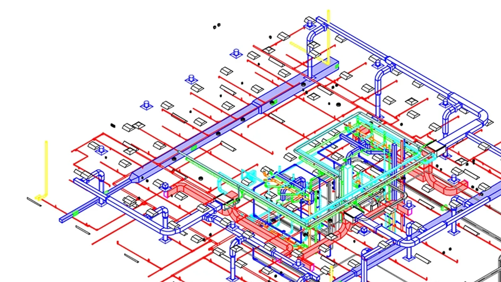
Ductwork, sprinkler pipes and plumbing in one ceiling zone. Every crossing here is a place where a clash test has to prove there is room. Project: BIM MEP Portfolio by Katta Ashwini Reddy on Behance.
Every clash detection guide explains that software finds collisions between models. Few show what a clash report looks like on a real project, or how much of it is noise. So we took the published coordination models of a real residential building, ran them against each other and sorted every result with explicit rules. The numbers are below, and they change how you should set up a clash test.
This guide is for BIM coordinators, architects and engineers who run or receive clash reports, and for contractors and owners who buy clash detection as a service. It covers what clashes are, the coordination process, Revit and Navisworks step by step, the software options (including free ones), a clash matrix you can copy, and what to ask a clash detection provider for.
What is clash detection in BIM?
Clash detection is the automated check of a federated BIM model, the combined models of architecture, structure and building services (MEP), for places where elements occupy the same space or violate a required clearance. Each finding is a clash, recorded with the two elements involved, their location and how far they overlap.
It exists because each discipline models its own system in its own file. The structural engineer places a beam, the mechanical engineer routes a duct, and neither sees the other's work until the models are combined. On drawings, the conflict surfaces on site, when the duct installer finds the beam. In a coordinated BIM process, it surfaces weeks earlier on a screen.
| Clash type | What it means | Example |
|---|---|---|
| Hard clash | Two elements physically intersect | A duct passing through a steel beam |
| Soft clash (clearance) | An element is inside another's required clearance zone | A pipe 20 mm from a beam where insulation needs 50 mm, or a valve with no space to reach it |
| Duplicate | The same element exists twice, often in two models | The architect's copy of the structural slab overlapping the engineer's slab |
| Workflow (4D) clash | A conflict in time rather than space | Two trades scheduled in the same area, or a crane path over unfinished work |
Navisworks names its standard test types after the first three: Hard, Hard (Conservative), Clearance and Duplicates. Workflow clashes need a model linked to the construction programme.
We ran a clash test on a real project: what 2,611 clashes meant
To see what clash detection produces in practice, we used the Schependomlaan dataset: the coordination models of a real residential building in Nijmegen in the Netherlands, made available by the project team with the data owners' permission for scientific and academic use. We publish only our aggregate results and charts, none of the model content. It contains the architect's model and separate models from the subcontractors: steel structure, hollow-core floors, precast stairs and balconies, and building utilities. All of them share one coordinate system, so they federate without moving anything.
We tested each subcontractor model against the architecture, and the utilities and steel against the floors, after leaving out finishes, fasteners and reinforcement, as a coordinator would. Then we sorted every clash:
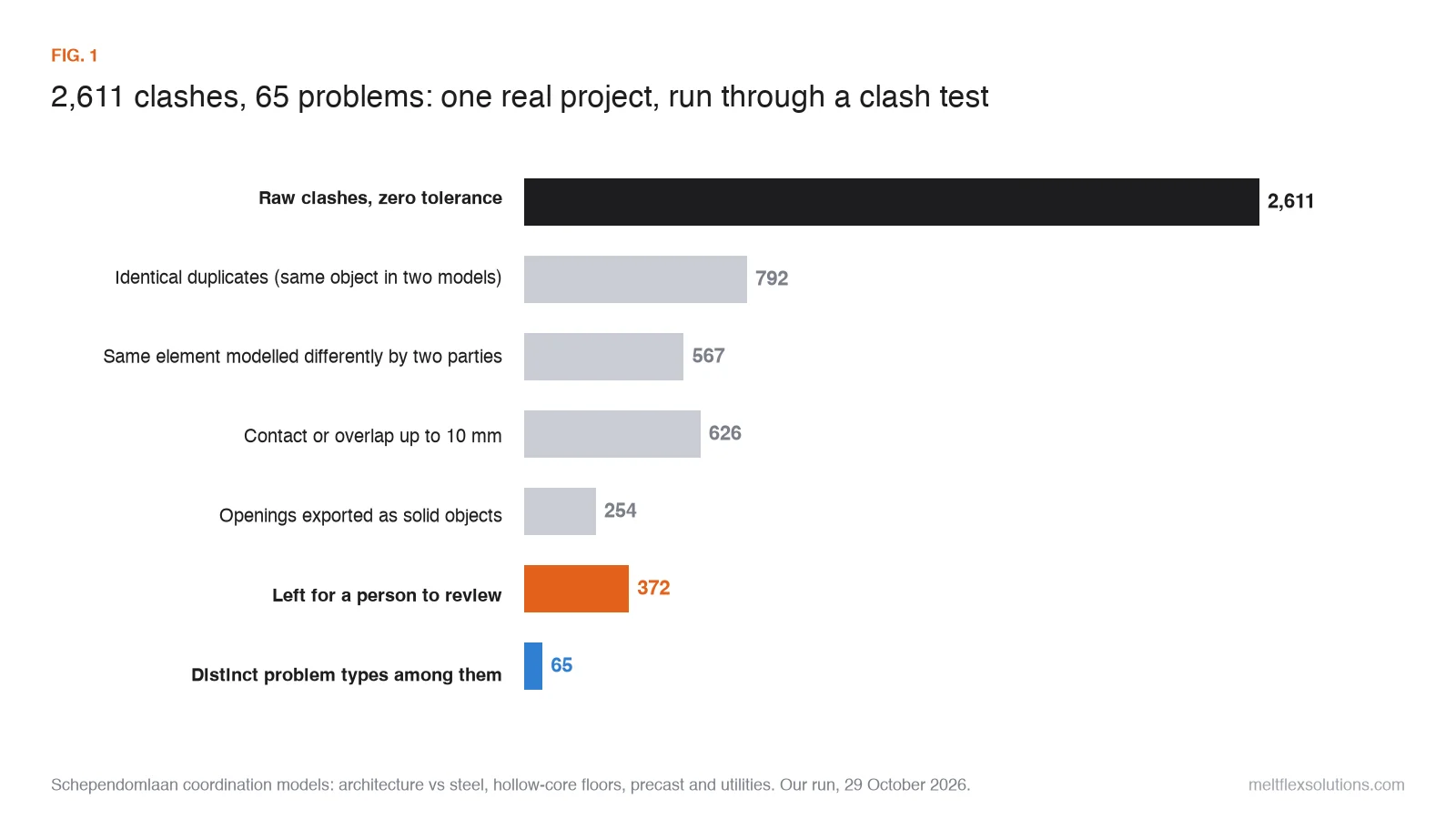
What the categories are, and what each teaches:
- 792 identical duplicates (30%). The architect's model contains its own copies of the steel beams, floor slabs and stairs that the subcontractors also modelled. Every copy collides with the original. This is the single largest source of noise, and a duplicates test (or simply switching off the copied categories) removes it before the real tests are run.
- 567 elements modelled twice, differently. The floor subcontractor modelled each hollow-core plank, bearing ledge and insulation strip; the architect modelled the same floor as one slab. They overlap almost everywhere without being identical, so a duplicates test does not catch them. The fix is agreeing who owns which element before modelling starts.
- 626 contacts up to 10 mm. Beams bearing on walls, slabs touching their supports: elements that are meant to meet. With a zero tolerance, every one of them is a "clash".
- 254 openings exported as solid objects. The floor model contains its planned openings (named "SPARING", Dutch for recess) as solid elements. Each pipe that passes through its planned opening therefore appears to clash with it. The opening is doing its job; the export is wrong.
- 372 left for a person. These are the clashes deeper than 10 mm that none of the rules explain, such as utility pipes running through foundation beams and floor slabs where no opening is modelled, and steel columns cutting through timber-frame wall elements. 186 of them are deeper than 50 mm.
Grouped by which two kinds of element collide, the 372 clashes are 65 distinct problems, and just 23 of those groups account for 70% of them. That is the number a coordination meeting should discuss: 65 issues, not 2,611 clashes.
Tolerance changes everything
The same models, counted again at different tolerances (the minimum penetration that counts as a clash):
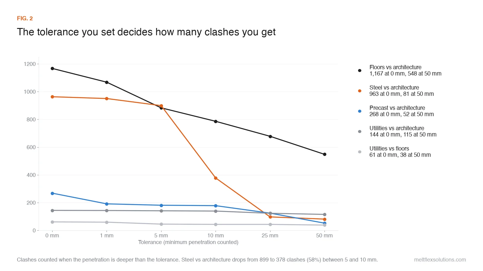
Two lessons from that chart. First, the right tolerance is different for each pair of models. Steel against architecture lost 58% of its clashes between 5 and 10 mm, because most of them were bearings and connections; utilities barely changed, because a pipe through a slab is either a real problem or a missing opening, whatever the tolerance. Second, a tolerance high enough to make a report look clean (50 mm) still hides real problems: 115 utility clashes survived it.
What our test could not do, honestly stated: about 30% of the utility pairs (1,226 of 4,119) could not be checked at all, because the utility objects were exported as open surfaces rather than closed solids. That is a real coordination finding in itself: an MEP export that cannot be clash-tested should be sent back. Our sorting rules also rely partly on element names, which a coordinator would normally confirm by looking at each group.
The clash detection process, step by step
Clash detection is one step in a coordination cycle that repeats, often weekly, through design and construction:
- Agree the setup in the BIM execution plan. Shared coordinates and levels, who models what (this alone would have removed 1,359 of our 2,611 clashes), file naming, export settings, and the clash matrix below.
- Collect and federate the models. Each discipline exports its model on an agreed day, usually as IFC or as Navisworks cache files (NWC), and the coordinator appends them into one federated model.
- Run the tests in the clash matrix. One test per pair of disciplines, each with its own type and tolerance, plus a duplicates test per model.
- Group and filter. Group clashes by location, level, system or element type so each group becomes one issue. Remove the known noise (approved penetrations, temporary works, items out of scope).
- Assign issues. Each issue gets a viewpoint, a screenshot, a description, a responsible discipline and a due date. The open format for passing issues between tools is BCF (BIM Collaboration Format) from buildingSMART.
- Discuss in the coordination meeting. Agree who moves: usually the more flexible system (small pipes before ducts, ducts before structure), unless a design decision is needed.
- Fix in the authoring models. Changes are made in Revit, Archicad or the fabrication model, never in the federated model.
- Re-run and track. The next cycle shows which issues are resolved, which are new and which keep coming back. A falling count of open issues per cycle is the measure of progress.
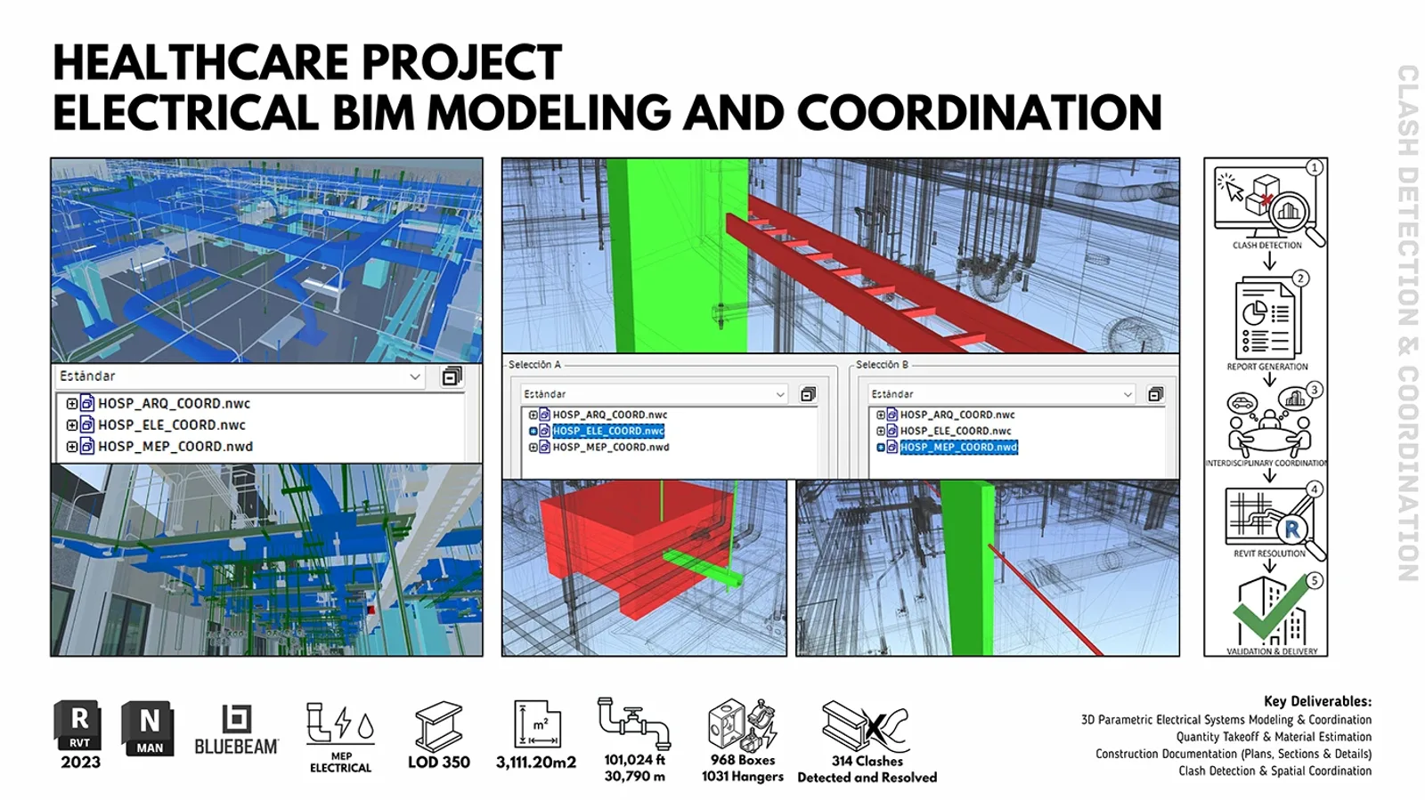
A real coordination setup: architecture, electrical and MEP models appended in Navisworks, tested against each other in Clash Detective, then resolved in Revit. The author reports 314 clashes detected and resolved on this healthcare project. Project: Healthcare Project, Electrical BIM Modeling by Juan Ramirez Vasquez on Behance.
A clash matrix you can start from
A clash matrix lists which models are tested against which, with what test type and tolerance. There is no standard one; the right values depend on the project, the stage and the trades. The table below is our starting template, informed by the test above, and it should be agreed and adjusted in your BIM execution plan:
| Test | Type | Starting tolerance | Why |
|---|---|---|---|
| Each model against itself | Duplicates | 0 mm | Removes double-modelled elements before anything else |
| Structure vs architecture | Hard | 10 mm | Bearings and connections are meant to touch; our steel test lost 58% of its noise at 10 mm |
| MEP (ducts, pipes) vs structure | Hard | 0 to 5 mm | Any real penetration of a beam or slab needs an opening or a structural check |
| MEP vs structure | Clearance | 25 to 50 mm | Insulation, hangers and installation space |
| Ducts vs pipes vs cable trays | Hard and clearance | 0 mm, then 25 mm | Trades must fit together in the same ceiling zone |
| MEP vs ceilings and walls | Hard | 5 mm | Finds services below the ceiling line or through walls without openings |
| Openings and sleeves | Excluded or tested separately | n/a | Planned penetrations should not count as clashes; check they exist instead |
Clash detection in Revit: Interference Check
Revit has a built-in clash tool called Interference Check (Collaborate tab, Coordinate panel). It is quick for checking your own model or your model against one consultant's link:
- Open Interference Check and choose Run Interference Check.
- On the left, pick categories in the current project (or a link); on the right, the categories to test against, in the current project or in one linked model.
- Run the check. Revit lists each interference with both element IDs; selecting one highlights it so you can Show it in a view.
- Export the report to HTML, or use Show Last Report to reopen it later. Refresh reruns the check after changes.
Its limits are why most projects still coordinate elsewhere: it compares the current model against one link at a time, it has no penetration tolerance, it cannot group or assign clashes, and the exported report is a static snapshot. Use it as a designer's self-check before sharing a model, not as the project's coordination process.
Clash detection in Navisworks: Clash Detective
Navisworks is the most common coordination tool on Autodesk-based projects. Note the editions: Clash Detective is only in Navisworks Manage. Navisworks Simulate does not have it, and the free Navisworks Freedom can open and view an NWD file, including a model someone else has prepared, but cannot run clash tests.
The workflow in Navisworks Manage:
- Append the discipline models (NWC exports from Revit, IFC, DWG and others) into one federated file.
- In Clash Detective, add a test and choose Selection A and Selection B (models, categories or saved search sets).
- Set the type (Hard, Hard (Conservative), Clearance or Duplicates) and the tolerance.
- Run the test, then group the results and give each group a status (New, Active, Reviewed, Approved or Resolved) and an assignee.
- Export a report with viewpoints, and save the file so the next run can show what changed.
This overview from Man and Machine, an Autodesk partner, walks through Clash Detective, from simple duplicate checks to rule-based tests:
Clash detection software compared
| Software | Clash detection | Works with | Cost |
|---|---|---|---|
| Navisworks Manage | Clash Detective: hard, clearance, duplicates, grouping, statuses, reports | NWC from Revit, IFC, DWG and many formats | Paid subscription; Freedom viewer is free but cannot clash |
| Revit | Interference Check: one model against one link, no tolerance | Revit models and links | Included in Revit |
| Autodesk Construction Cloud, Model Coordination | Automatic clash detection in the cloud as models are published | Revit, IFC and Navisworks files | Paid |
| Solibri Office | Clash and rule-based model checking, strong on IFC | IFC | Paid |
| BIMcollab Zoom | Clash detection and smart issues, with BCF | IFC | Free viewer; clash detection needs a licence |
| Revizto | Clash automation with issue tracking for the whole team | Revit, Navisworks, IFC and more | Paid |
| IfcClash (IfcOpenShell), also in Bonsai | Intersection, collision and clearance checks, BCF export | IFC | Free and open source |
If you work in IFC and have no budget, IfcClash (inside the free Bonsai add-on for Blender, or from the command line) is a real option, and BCF lets you pass its results to anyone. For the authoring tools themselves, see our comparison of the best BIM software.
What to ask a clash detection service for
Clash detection and MEP coordination are often bought as a service, especially by contractors. A good provider should deliver more than a PDF of red and green screenshots:
- The clash matrix and tolerances, agreed with you before the first run.
- Grouped issues, not raw clashes. Ask how many raw clashes became how many issues. A report with thousands of items has not been worked.
- BCF files with a viewpoint, screenshot, responsible party and due date for each issue, so they open in your own tools.
- A trend report each cycle: issues opened, resolved and still open.
- What was excluded and why: duplicates removed, openings filtered, models that could not be checked because of bad geometry.
- Coordination meeting minutes with decisions, not just findings.
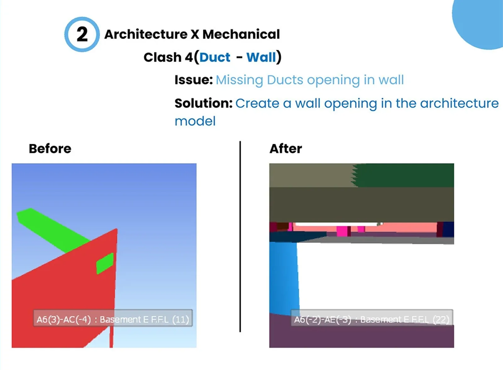
A typical issue written up properly: architecture against mechanical, a duct through a wall with no opening, fixed by adding the opening in the architectural model. Project: BIM Diploma Coordination, Clash Detection and Resolution by Mohamed Nehad on Behance.
Common clash detection mistakes
- Running everything against everything at zero tolerance. The result is thousands of clashes nobody reads. Use a matrix and a tolerance per test.
- Not removing duplicates first. In our test they were 30% of all clashes.
- Counting planned openings as clashes, or the opposite, never checking that planned openings actually exist.
- Reporting clashes instead of issues. People fix problems, not lists of element pairs.
- Fixing the federated model. Changes belong in the authoring model, or the clash comes back next week.
- Accepting models that cannot be tested. Open or broken geometry hides clashes. Ask for a corrected export.
- Starting too late. Clash detection on a model that is already in fabrication finds problems when they are expensive to fix.
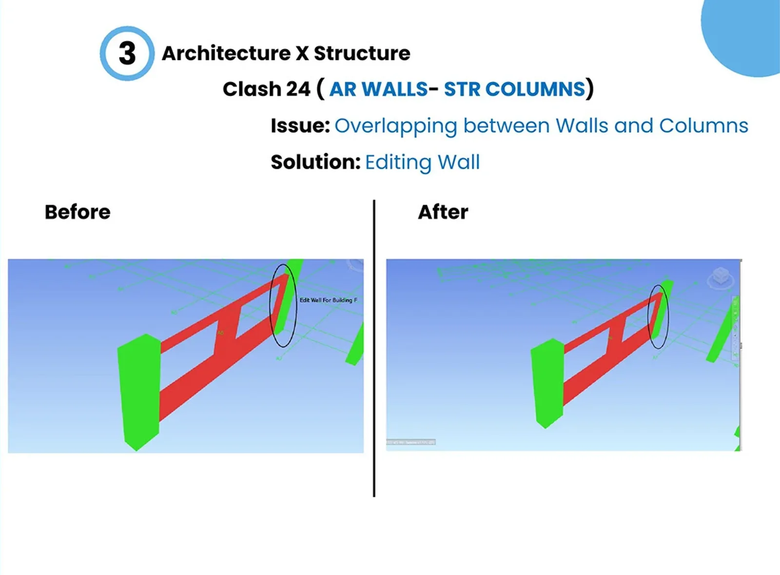
Architecture against structure: a wall running into a column, resolved by editing the wall. Simple, but only once someone has decided which discipline moves. Project: BIM Diploma Coordination, Clash Detection and Resolution by Mohamed Nehad on Behance.
If you are coordinating models of an existing building, the as-built model usually comes from a laser scan; our guide to Scan to BIM covers how to order and check one.
Frequently asked questions
What is clash detection?
Clash detection is the automated check of combined BIM models for places where elements from different disciplines intersect or come closer than an agreed clearance, such as a duct through a beam or a pipe through a wall with no opening. Each finding is reported with the elements involved and their location, so it can be resolved in the design before construction.
What is clash detection in BIM?
In BIM, clash detection is one step of the coordination process: the architecture, structure and MEP models are federated, tested against each other according to a clash matrix, and the results are grouped into issues, assigned to the responsible discipline (often as BCF files) and tracked until they are resolved in the authoring models.
What is the difference between a hard clash and a soft clash?
A hard clash is a physical intersection of two elements, such as a pipe through a beam. A soft clash, or clearance clash, means an element is inside the space another element needs, for insulation, maintenance access or installation, even though they do not touch. Clearance tests use a distance, for example 25 or 50 mm.
Can Revit do clash detection?
Yes, with Interference Check on the Collaborate tab. It compares categories in the current model against each other or against one linked model and exports an HTML report. It has no tolerance setting and cannot group or assign clashes, so most projects use it for self-checks and run project coordination in Navisworks, Solibri or a cloud platform.
Is there free clash detection software?
Yes. IfcClash, part of the open-source IfcOpenShell project and available inside the free Bonsai add-on for Blender, runs intersection, collision and clearance checks on IFC models and exports BCF. The free BIMcollab Zoom viewer opens IFC but needs a licence for clash detection, and Navisworks Freedom cannot run clash tests.
What tolerance should I use for clash detection?
There is no single right value; it depends on the pair of models. In our test on a real project, steel against architecture lost 58% of its clashes between 5 and 10 mm because they were bearings and connections, while utility clashes barely changed. A common approach is around 10 mm for structure against architecture, 0 to 5 mm for services against structure, and a separate clearance test of 25 to 50 mm where space is needed.
What is a clash matrix?
A clash matrix is a table that defines which models or element groups are tested against each other, with which test type (hard, clearance, duplicates) and tolerance, and often the priority and responsible party. It is agreed in the BIM execution plan so every coordination cycle runs the same tests.
How many clashes are normal on a project?
Raw counts mean little. On the real project we tested, 2,611 raw clashes at zero tolerance came down to 372 that needed review and 65 distinct problems after removing duplicates, double-modelled elements, contacts and openings exported as solids. What matters is the number of grouped issues and whether it falls from one coordination cycle to the next.
How we made this guide
The clash test is our own work. We used the Schependomlaan coordination models (architecture, BERNTS steel structure, WAARDO hollow-core floors, MULTICOM precast and the utilities model), from the openBIMstandards archive on GitHub (DOI 10.17605/OSF.IO/NE2YU), where the data owners grant use for scientific and academic purposes; we publish only aggregate results. We read the IFC files with IfcOpenShell 0.9, left out coverings, building element parts, fasteners, accessories, reinforcement and assemblies, found candidate pairs by bounding box, and computed the exact intersection of each pair of closed solids with the manifold3d geometry library. Penetration depth is the smallest dimension of the intersection solid, a simple stand-in for the penetration distance that clash tools report. Duplicates are intersections covering at least 90% of the smaller element; the other categories use rules on element types and names, described above. The run took place on 29 October 2026. We did not have the project team's own clash reports to compare against, and the models date from the project's coordination phase, not its final state.
Tool features (Revit Interference Check, Navisworks editions and clash test types, BIMcollab Zoom licensing, IfcClash) were checked against vendor documentation on the same day. The clash matrix is our recommendation, not a published standard. Search demand was checked in Ahrefs Keywords Explorer: questions about what clash detection is, how it works in Revit and Navisworks, which software to use and clash detection services make up most searches on the topic.
The author, Matúš Koleják, builds BIM and IFC software at MeltFlex and wrote the analysis scripts; he does not run coordination meetings for a living. Disclosure: MeltFlex s.r.o., which publishes this blog, also makes AIBIMTool, the AI BIM tool in the sidebar. It generates new BIM models and is not a clash detection tool, so it plays no part in this guide, and no software here paid to be mentioned.
Sources and further reading
- Schependomlaan coordination dataset (openBIMstandards on GitHub, DOI 10.17605/OSF.IO/NE2YU): the models used in our test.
- Autodesk Navisworks help, clash test types: Hard, Hard (Conservative), Clearance and Duplicates.
- Autodesk Navisworks glossary, Clash Detective: availability in Navisworks Manage and the role of tolerance.
- Autodesk Revit help, Interference Check.
- BIMcollab help center, how to perform a clash detection with BIMcollab Zoom.
- IfcOpenShell and Bonsai: the open-source IFC toolkit with IfcClash.
- buildingSMART, BCF-XML: the BIM Collaboration Format specification.
Running clash reports nobody reads, or coordinating issues by email and screenshots? Book a free call and we will show you which parts of that work can be automated.
Image credits: charts by MeltFlex Solutions from our own clash test. All other images are published BIM coordination projects on Behance, credited under each picture, cropped to fit the page and otherwise unedited: Katta Ashwini Reddy, Juan Ramirez Vasquez and Mohamed Nehad.
More articles
Share article