Sketch to DXF: Turn a Hand Drawing Into a CNC or Laser-Ready File
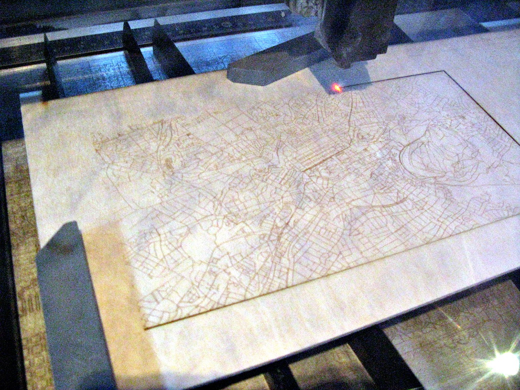
A laser cutter and a CNC machine do not care how good your idea is. They care about one thing: clean vector paths, in a file they can read. That file is almost always a DXF. So the real question for a maker, a fabricator or a small workshop is not "can AI draw," it is "can I get my hand sketch into a cutter-ready DXF without redrawing the whole thing in CAD."
The short answer is yes, much faster than a few years ago. The honest answer is that it converts the geometry, not the engineering, and there are checks you must run before you send anything to a machine. Here is how it actually works.
Why your machine needs a DXF, not a photo
A photo of your sketch is a raster image: a grid of pixels with no idea where a line starts or ends. A cutter needs vectors: actual paths, arcs and lines with real coordinates it can follow with a tool head.
DXF, the Drawing Exchange Format, is the common language for this. Almost every CAM program, laser controller and CNC toolchain can import it, which is why it has outlived most of its rivals. Turning a sketch into a DXF means tracing your pixels into clean vector geometry, then exporting it in that format. That tracing step, the raster to vector conversion, is the part AI now does well.
How AI converts a sketch to DXF, step by step
The workflow is simpler than it sounds, and it is the same whether you start from paper or a tablet drawing.
- Capture. Photograph or scan the sketch, straight on, in good even light.
- Vectorise. The AI traces the outline and internal lines into vector paths, cleaning up the wobble of a freehand line into something a machine can follow.
- Set the scale. This is the step people skip and regret. A drawing is useless to a cutter until it knows that one line is, say, 200 millimetres and not 200 pixels. You anchor the scale to a known dimension.
- Export DXF. You save the cleaned geometry as a DXF and open it in your CAM software, LightBurn for a laser or Fusion 360 and AutoCAD for CNC, or whatever drives your machine.
- Verify before you cut. You check the key dimensions against your intent, because the next thing that happens is a tool turning real material into either a part or scrap.
Once the geometry is a clean DXF, the machine does the rest. Everything upstream is about getting those vector paths right.
What converts well, and what does not
The cleaner the input, the cleaner the DXF. This is the single biggest lever you control.
Converts well:
- Bold, single-weight lines drawn with a dark pen on white paper.
- Flat, straight-on geometry: a bracket, a gasket, a sign, a panel, a profile.
- Clear corners and closed shapes, where it is obvious what is inside and what is outside.
Converts badly:
- Pencil, shading, hatching and cross-outs, which the tracer reads as more lines.
- Perspective drawings, where a 3D view has to be guessed back into a flat shape.
- Tiny detail crammed together, where two close lines merge into one.
If your sketch is a clean flat outline, you are most of the way there. If it is an artistic perspective sketch with shading, expect to do real cleanup.
How accurate is it really
Here is the reality check, because this is where a cut part goes wrong.
AI is good at capturing the shape. It is not the source of truth for dimensions. The vectoriser will happily trace a slightly wonky freehand circle into a smooth curve, but it does not know your circle was meant to be exactly 50 millimetres. Scale and critical measurements come from you, set against a known reference and then checked in CAD.
For laser and CNC work the stakes are physical: material, machine time, and tolerances that have to fit a real assembly. So treat the DXF as a fast, accurate first draft of the geometry, and treat the dimensions as something you confirm before the machine moves. That split is exactly why we built TechDraw AI to produce a clean, editable technical drawing rather than a locked image, so you can correct a dimension instead of starting over.
The geometry can come from AI. The dimensions and the sign-off still come from a person, before anything reaches the machine.
How to prep your drawing for the best result
A few minutes of prep beats an hour of cleanup later.
- Draw on plain white paper with a dark, consistent pen, not pencil.
- Use a ruler for anything that needs to be straight, and mark at least one real dimension so you can set the scale.
- Keep it flat and orthographic: draw the face you want to cut, not a 3D view of it.
- Photograph it square on, filling the frame, with no shadow falling across the lines.
- Erase construction lines and stray marks before you capture, because the tracer cannot tell them from the real outline.
DXF, DWG and SVG, and which one you want
The format names trip people up, so here is the quick version:
| Format | Best for | Editable in CAD | Reads on most cutters |
|---|---|---|---|
| DXF | CNC and laser cutting | Yes | Yes |
| DWG | AutoCAD-based workflows | Yes | Sometimes |
| SVG | Laser engraving, design tools | Limited | Engraving yes, CNC less |
In practice: DXF is the interchange format almost every machine and CAM tool reads, so for CNC and laser it is usually your target. DWG is AutoCAD's native format, richer but less universally supported by cutter software. SVG is great for laser engraving and design tools like Inkscape or Adobe Illustrator, but for dimensioned mechanical parts a DXF keeps you in the CAD and CAM world more cleanly.
For a part you intend to cut, export DXF, confirm it opens correctly in your machine software, and keep the editable source so the next revision is a tweak and not a redraw. We cover the broader picture of this in our guide on sketch to CAD with AI.
Where a human still wins
AI converts lines. It does not understand fits, tolerances, material thickness, kerf, or whether your bracket will actually hold the load. It will not tell you that two parts will not assemble, or that a slot needs to allow for the width of the laser beam.
The makers getting real value are not pretending the AI is an engineer. They use it to delete the slow redraw between a good sketch and a cuttable file, then bring their own judgement to the dimensions and the fit.
The goal was never to replace the drafter. It is to delete the tedious redraw that sits between a good sketch and a finished part.
Frequently asked questions
Can I really turn a hand drawing into a DXF for laser cutting?
Yes. The AI traces your sketch into vector geometry and exports a DXF your laser software can read. The one thing it cannot do for you is invent the scale, so you set and confirm the real dimensions before cutting.
Will the dimensions be accurate enough to cut from?
The shape will be close. The exact measurements are on you to set against a known reference and verify in CAD. For anything that has to fit another part, always check the critical dimensions before you run the job.
What is the difference between sketch to CAD and sketch to DXF?
Sketch to CAD is the general idea of turning a drawing into editable CAD geometry. Sketch to DXF is the specific output most CNC and laser workflows actually need, because DXF is the format their software imports.
What kind of sketches convert worst?
Pencil shading, perspective views, and cramped detail. Bold flat outlines on white paper convert best.
Do I still need CAD software?
For a quick one-off cut, often not much. The moment you need precise tolerances, parametric edits, or an assembly that fits together, you want proper CAD like Fusion 360 or AutoCAD, with the converted DXF as your starting point rather than a blank canvas.
Sources and further reading
- Converting paper drawings to CAD - Scan2CAD guide to scanning and vectorising hand drawings.
- DXF format overview - background on the Drawing Exchange Format and why it is so widely supported.
Image credits: hero photo by Steven Kay, via Wikimedia Commons, licensed under CC BY 2.0. Technical drawing photo via Pexels.